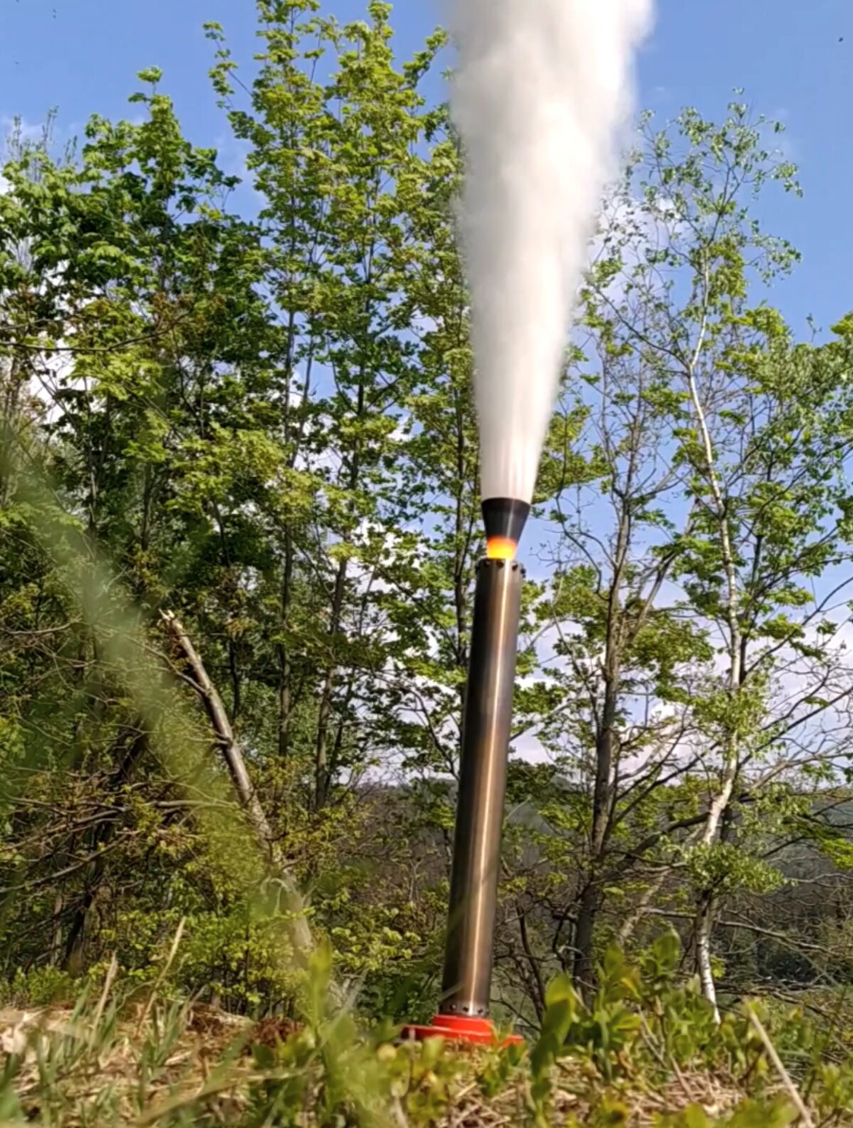
Rocket motor test stand
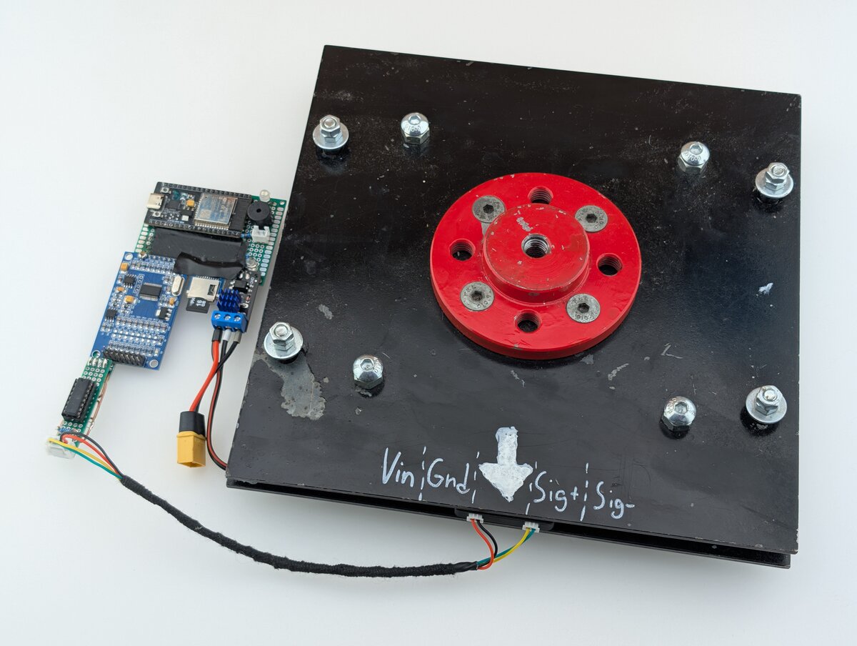 The goal of this project is to make a fully integrated test stand for rocket motors. This project started my classmate, but we quit working on it after finishing high school. After about 5 years I decided to completely overhaul it. The requirements I set for this project are:
- maximum measured thrust of at least 200kg
- logging to an SD card with a frequency of at least 1000Hz
- no logging dropouts
- capability of igniting the rocket motor
- button on a long wire to start the test
- audio and visual signalization of the test state
Mechanical design
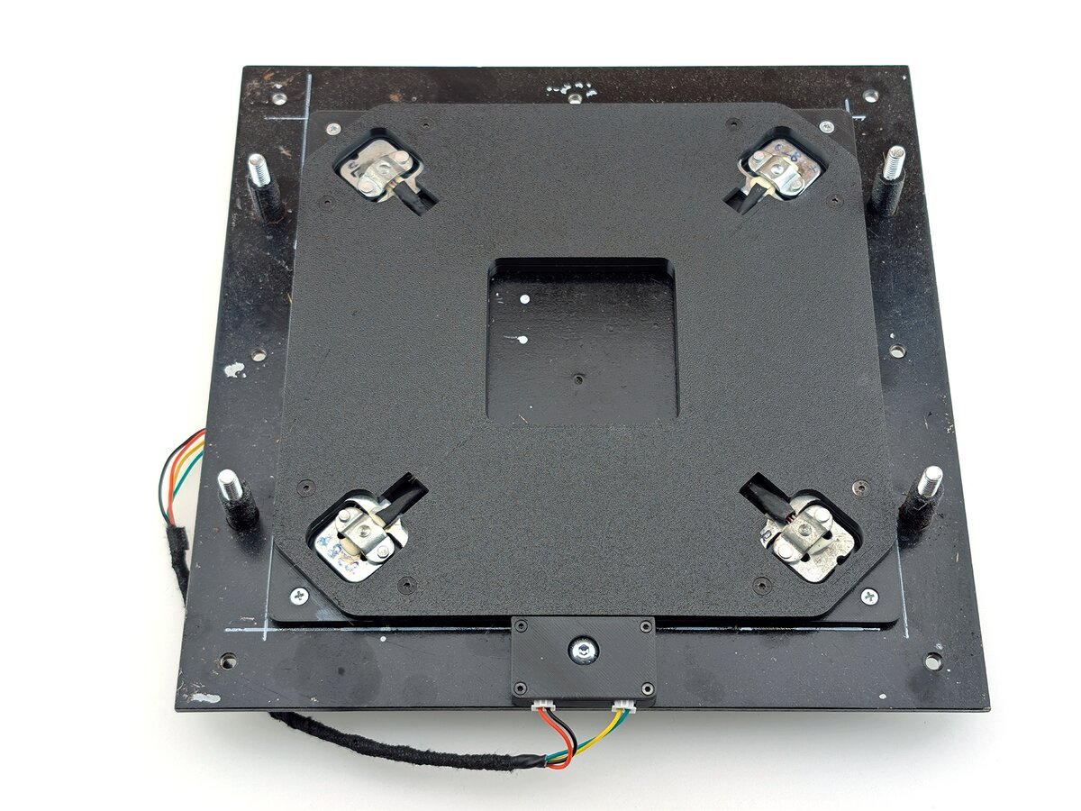
The main structure of the test stand is made out of 2 steel plates to make it rigid. The top plate has a removable interface for the rocket motor. It also has 4 M10 screws with lock nuts, which act as adjustable contact points for the load cells underneath. The bottom plate houses the load cells with their wiring and connectors. The plates are connected using 4 feet, which allow them to slide freely in the vertical direction.
Electrical design
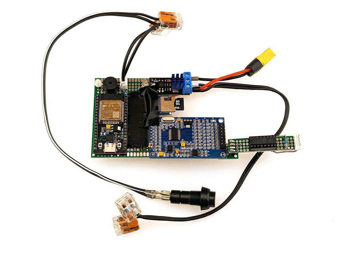
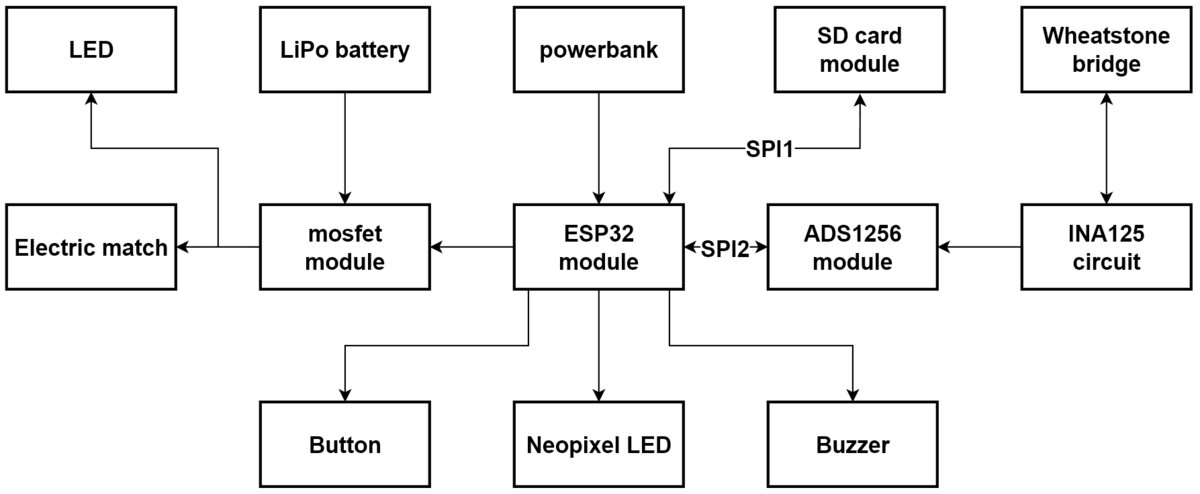
The electrical design is done by connecting multiple breakout boards. The MCU module is an ESP32-wroom and the project is powered by its LDO. The power comes from a powerbank connected to the USB-C.
Load cells
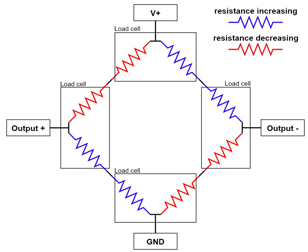
The thrust is measured by 4 50kg load cells. Each load cell has 2 strain gauges in it. The resistance of one of those increases with pressure and decreases for the other one. It is important to connect them in a specific way for them to work in a wheatstone bridge:
Analog to digital converter
The wheatstone bridge outputs 2 analog signals. The voltage of one increases with load and decreases for the other one. This analog signal needs to be converted to a digital signal so it can be handled by the MCU. The ESP32 has ADC feature, but the resolution and accuracy is poor. Most projects like this use the HX711 ADC, but measures 80 samples per second at most. I decided to use a ADS1256, because it can measure up to 30 000 samples per second and the Arduino library from the CuriousScientist makes it easy to work with. Most ADCs including this one also include a programmable gain amplifier (PGA), which subtracts the two signals and amplifies it. The PGA of the ADS1256 can amplify the signal up to 64x.
Instrumentation amplifier
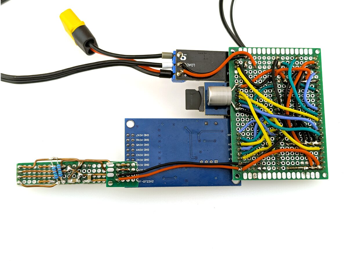
After a bit of testing I found out that I need to amplify the signal around 800x to utilize the whole range of the ADS1256. This meant I needed to add an instrumentation amplifier (IA). At first I wanted to buy a module like the other components. The problem is that I could only find modules with knock off IAs with questionable performance. I therefore decided to buy the IA from reputable source and build the module myself. I chose the INA125P, because it is made for this application and also includes a precision voltage reference, which I can use for the wheatstone bridge. Since it's rather expensive, I also bought a socket for it so I can later remove it. My schematic is based on the example schematic from the datasheet.
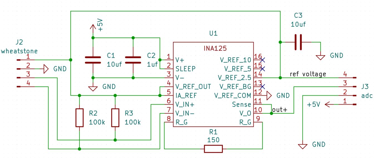
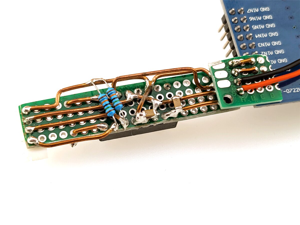
At first, I wanted to make a custom PCB, but I later decided to make the circuit on a protoboard.
Motor ignition circuit
The test stand uses an N-channel mosfet module to ignite the electronic match. This allows it to use 2 separate power supplies for the electronic match and for the electronics. The electronic match uses a 6s LiPo for ignition, which can provide very high current in case of a short, and it doesn't cause a brownout for the rest of the electronics. There is an LED wired to the output to warn you if the mosfet is closed.
Signalization
The test stand uses a single Neopixel LED and a buzzer for signalization.
Software
I am using ArduinoIDE for this project, as I have the most experience with it. The biggest challenge of this project was logging the data without any dropouts. The SD card has some internal process, which periodically freezes is for around 300ms. This freezes the program causing at best around 300 missed data points. This seems to be caused by writing certain amount of data. At some data rate the program is frozen for more time than it is logging. The solution for this is to run the SD card writing on a different task using the FreeRTOS tasks. This way when the SD card tasks freezes, the main task is still measuring the thrust. The SD card freeze also freezes the SPI lane. For this reason it needs its own SPI lane, which doesn't block other SPI devices. During the freeze, the measured data needs to be stored somewhere so it can be later written to the SD card. The simplest solution I found that works is a FreeRTOS queue. This is a buffer with a limited size to which the main task writes data and from which the SD card task reads the data. It is important to choose large enough size to cover the outages.
Performance
There were and still are a couple of issues that I am having with this test stand.
Noise
The voltage difference from the wheatstone is extremely small (around 0.025mV/kg before amplification), which makes it highly susceptible to noise. The early version of this test stand showed a prominent periodical peaking noise.
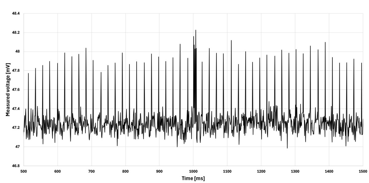
After a lot of testing I noticed that it correlates with the sd card activity. The fast transitions in the SPI lane must have caused a voltage to induce on the analog signal wires. I decided to move the IA module far away from the digital signal wires, which helped a lot. The only issue now is that it sticks out quite far.
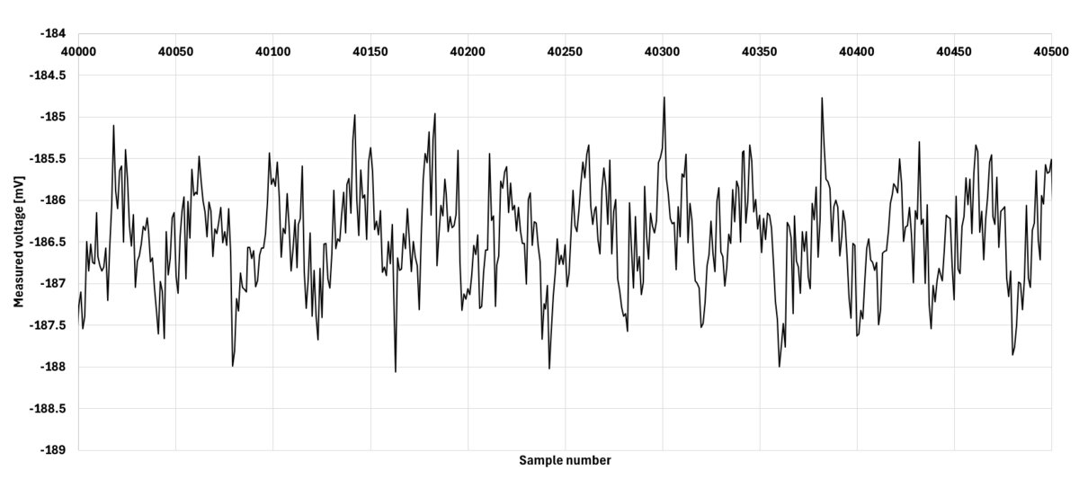
Another type of noise I noticed using an FFT has a frequency of exactly 50Hz.
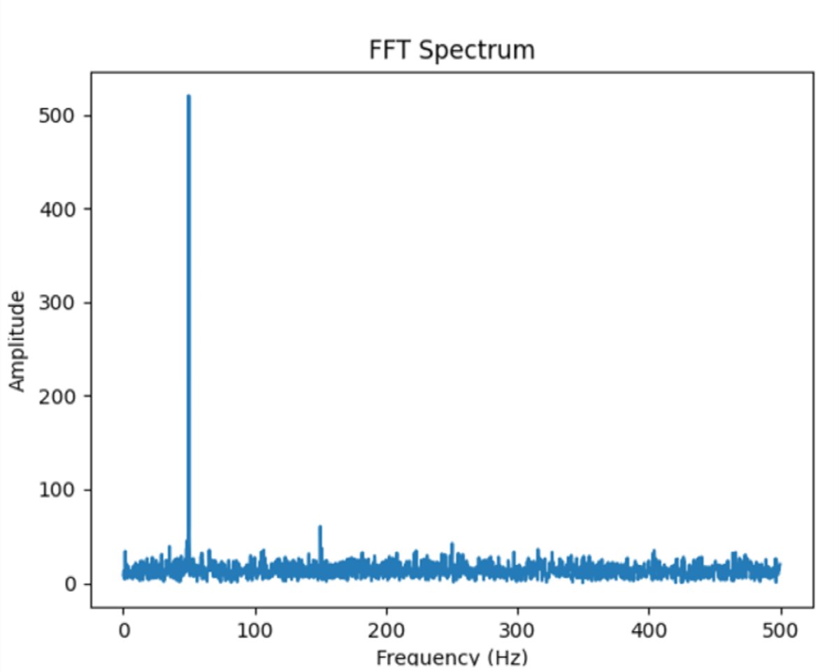
It is very obvious that this is caused by the power grid. It is even visible to a human eye with a moving average applied to the data:
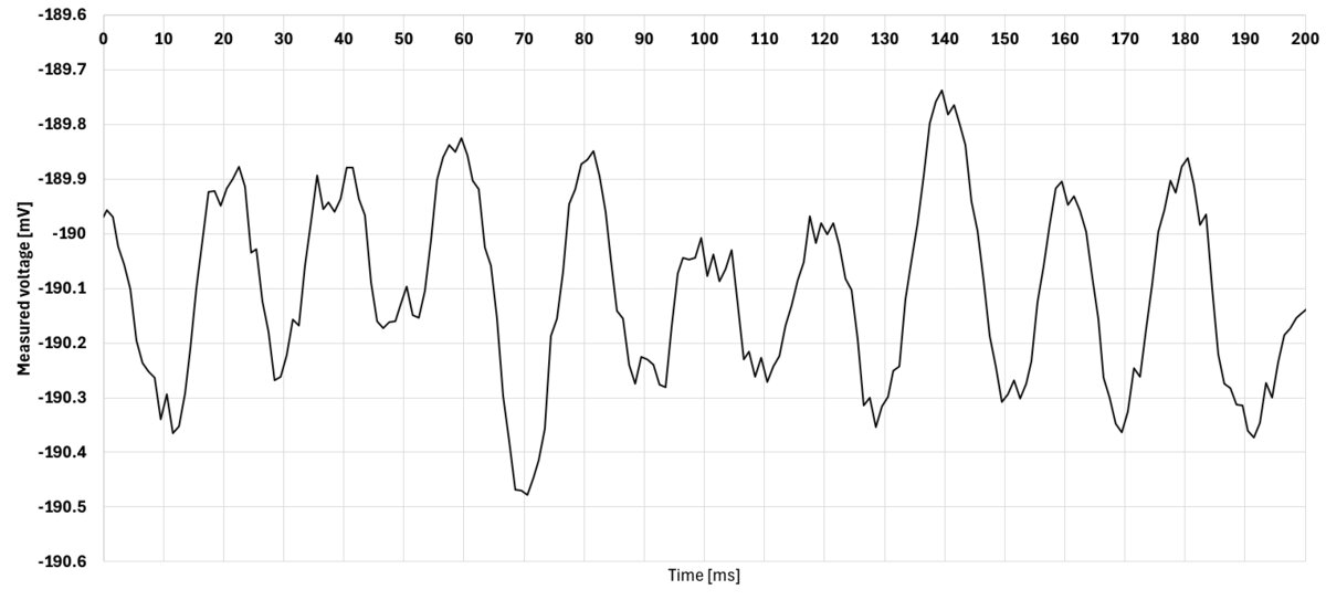
This should not be an issue as the tests will be done far away from the power grid. The noise amplitude of this system is around 2mV, which converts to 0.2kg of thrust. This is OK for large motors, but I would like to still reduce it. The main suspect for me is my IA module. It looks cool, but a normal PCB with a solid ground plane is going to perform better. Another issue are the wires connecting the wheatstone to the amplifier. They are not shielded and thus can pick up noise. Right now I am using 2.5V excitation voltage for the wheatstone bridge. Using higher voltage would allow me to reduce the IA amplification reducing the noise.
Settling time
I could not get the scale factor to be constant during my calibrations. It got higher as the time went on. This made me do a test where I left the test stand standing still for a long time.
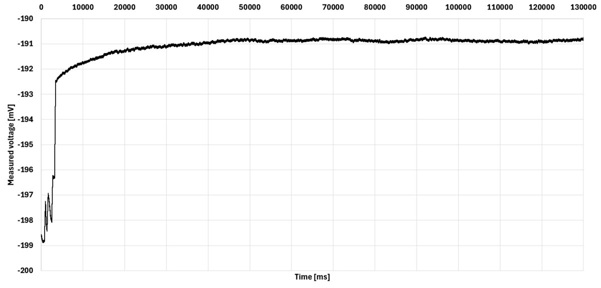
From this test I found out that the measured voltage changes until around 50 seconds of runtime. That is probably caused by the components heating up and changing their characteristics. This isn't a big issue. It just means that the test stand needs to be powered for about a minute before doing a motor test.
Here is an image from a motor test using this test stand: