
Kabrio fingertip mouse mod
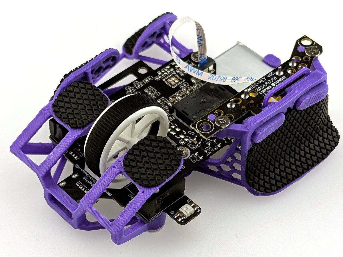
The goal of this project was to create the best mouse for my use case. I did that by making a custom 3D printed shell, which fits my hand size and grip perfectly and weighs only about 20 grams. You can download this mod on my Printables post: Kabrio mod.
Donor mouse
You obviously need the electronic internals for a mouse to work. Ideally I would like to make my own PCB and firmware, but that is beyond my skills for now. The other option is to buy a mouse, disassemble it and use its internals for your shell. I postponed this project for a long time, because high performance mice from the big brands are quite expensive. I later found out that you can buy chinese mice with the same performance for way cheaper, so I decided to try them out. I started with the VXE R1, because it was really cheap for its specifications. This worked fine for the early prototypes, but I later switched to VXE MAD R. The main advantage of the MAD R over the R1 is the lower weight and the lower encoder height. I got the first MAD R for 40 USD, but the price unfortunately keeps rising.
Design
This mod is designed for the fingertip grip, because it's the grip that I use mainly. Fingertip grip means that only the fingertips of your fingers are touching the mouse. This leaves most of the shell unused and therefore it can be removed to reduce the weight. This leaves you with a "skeleton" shell, which has been mainly popularized by OptimumTech and his Zeromouse Blade.
I made this shell with a couple of objectives that I had to balance out (highest priority at the top):
- Comfort
- Stiffness
- Usability (printability, number of supports, post-processing, assembly)
- Weight
Other requirements were:
- Printable on a FDM 3D printer
- Works with PLA
I started by modeling the PCB with the scroll wheel. The shell was modeled afterward in the context of the PCB and the scroll wheel.
First I defined 5 points in the space. Each one representing the intended finger position. I got the positions initially by measuring some of the mice I own and my own hand and tweaked them as the project went on. Every grip position is defined by its corresponding point.
Finger grips
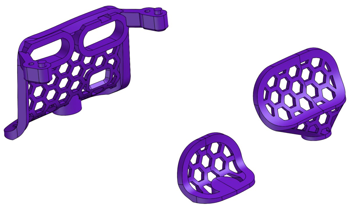
Comfort: The finger grips are modeled using a loft feature using multiple cross-section sketches and lead curves. They all have an aggressive curve up at the bottom to prevent your fingers from rubbing on the mouse pad. All the grips dip in the middle to make your fingers more secure and comfortable. The ring finger grip is lifted off the ground by a couple of millimeters to reduce the middle/ring finger distance, increasing the comfort.
Stiffness: The borders of the grips are thicker to increase their stiffness. There is a place to put a dot skate under each grip. This makes the load from the weight of your hand directly transfer into the mouse pad, removing any load from it on the rest of the shell.
Usability: The inside of each grip is modeled so that there isn't an overhang of more than 30 degrees coming from the print plate.
Weight: The grips have a negative hexagonal pattern in them to reduce the weight.
Thumb grip
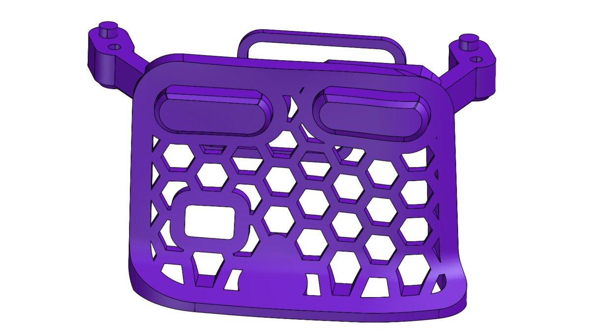
There was a lot of demand for this mod to include side buttons, so I decided to add a version with them in the latest release. The version with side buttons weights on average 3 grams more. The inclusion of the side buttons means that the thumb grip needs to be larger. The side buttons PCB is held down by 2 small arms and 2 small pins help the alignment. These arms unfortunately do need supports. The PCB needs to be mounted upside down in order to move the arms higher and make it possible to insert the main PCB. The side buttons themselves are printer separately and need to be inserted afterward. There are 2 lines of the same length connecting the 2 side buttons that act as stabilizers to prevent rotation during a press.
The small hole at the bottom left of the thumb grip houses the small protrusion of the main PCB. The thumb grip would have to be moved more to the left if the hole wasn't there, which would reduce comfort.
Front section
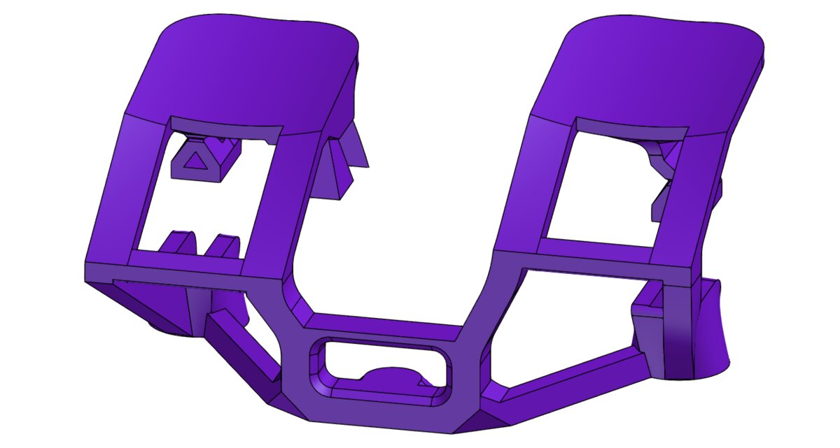
The front section of this mod was the hardest part to design right. Apart from the main objectives of this mod, this section adds a couple more. The first one is an optimal click feel. The second one is the scroll wheel housing.
Most mice use a compliant mechanism to make the buttons moveable. This mechanism is usually at the top of the buttons, where they are mounted. This solution could work for this mod, but it would add more parts, screws and additional assembly steps. The cleaner solution is to move the mechanism to the front as has been popularized by the Zeromouse. This makes it possible to print the buttons with the rest of the shell in one piece and allows the PCB to slide in from the back.
Most mods that utilize these button "paddles" move them to the sides in order to make space for the encoder and the middle button. While this is the simplest solution, it forces your index and middle fingers far apart, which is very uncomfortable for me. I therefore decided to move the paddles closer together and mold the shell around the encoder, scroll wheel and the middle click button.
The first feature of this section are the finger contact areas. They are simple extruded radii with a 10 degrees angle to the ground. The index finger contact patch is higher for 2 reasons. It tilts your arm a bit, reducing the strain on your wrist. It also makes space for the encoder, which is higher than the middle button.
Compliant mechanism
Let's assume the paddle is made out of 3 main components: the contact patch, the horizontal section coming out of it and the vertical section at the end. The compliant mechanism can be achieved by making the horizontal or vertical section weak and easy to bend. Let's make a simple analysis to determine the better solution.
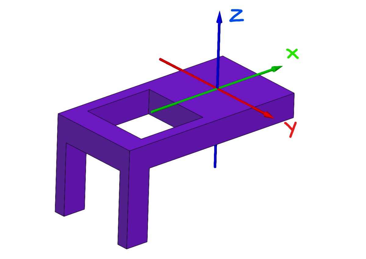 On the picture is a simple paddle that is fixed at the bottom. The goal of this paddle is to allow translation in the z axis and not allowing translation and rotation in the other axis. The two options are to make the horizontal part perfectly stiff and the vertical weak or vice versa.
Horizontal stiff and vertical weak
- Rotation:
- x: strong
- y: weak
- z: weak
- Translation:
- x: weak (function of y rotation)
- y: weak (function of z rotation)
- z: weak (function of y rotation)
Horizontal weak and vertical stiff
- Rotation:
- x: weak
- y: strong
- z: strong
- Translation:
- x: strong
- y: strong
- z: weak (function of y rotation)
From this simple analysis it is clear that the optimal solution is to make the compliant mechanism in the horizontal part of the paddle and make the vertical section as strong as possible.
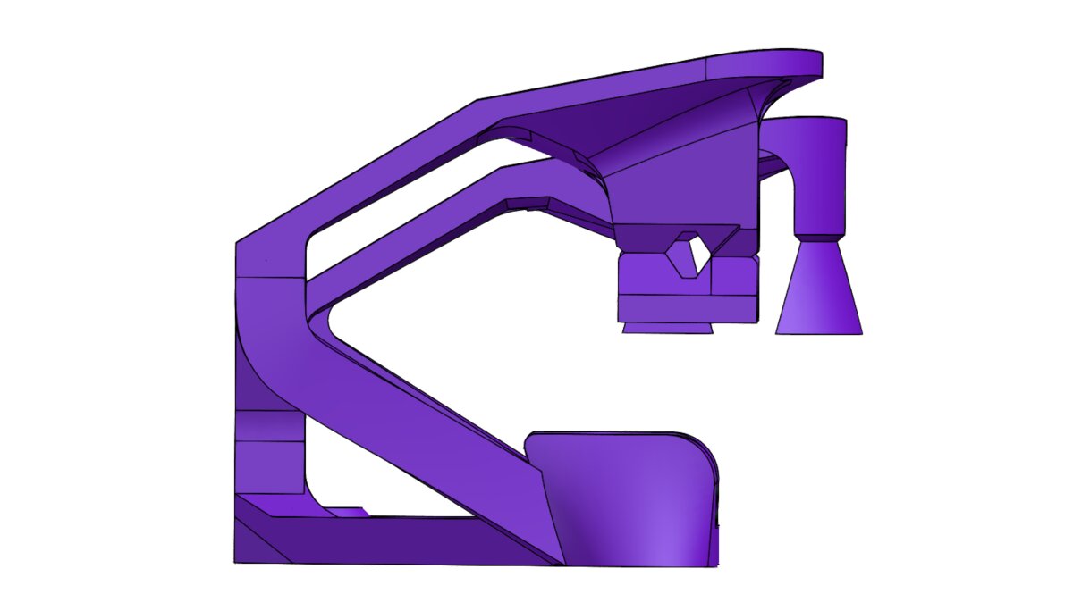 I decided to make the top paddle struts thinner than the bottom struts because of this. The top struts are not exactly horizontal, but angled at 30 degrees. This makes them a little bit less stable, but makes them printable without supports. That is really important, because removing the supports from these thin parts increases the risk of breaking them.
Plungers
On the underside of the contact areas of the paddles are plungers, which press the microswitches on the PCB. It is important to make the index and middle finger contact patches straight above these plungers. This way the load from the fingers is transferred straight into the microswitch. Placing the contact patches far away from the plungers results in a bending load during the click in the paddle, which makes the click feel mushy.
The design and tolerance of these plungers highly influences the click feel. The problem is that the plunger/microswitch contact patch faces down and thus needs supports. The Z height, layer height, material and support removal all influence the final tolerance of the plunger, which makes the button feel very inconsistent.
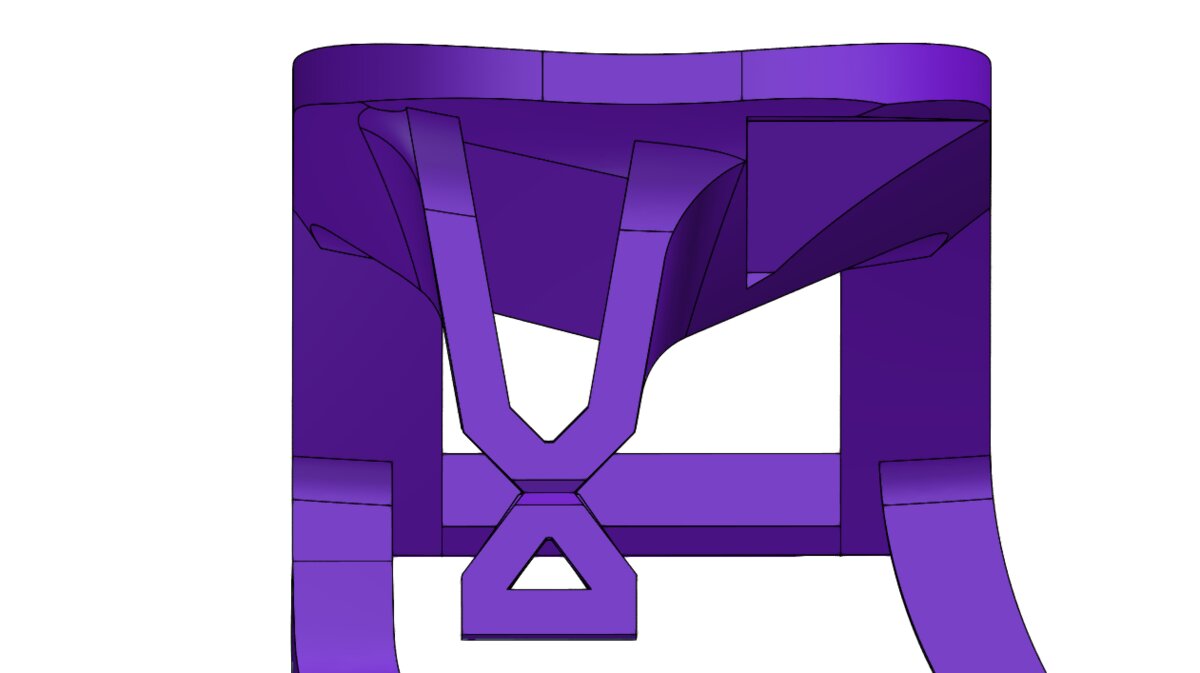 To prevent this inconsistency, I decided to connect the underside of each plunger to a sacrificial part, that is supposed to be snapped off. This moves the inconsistent support layer from the plunger to the sacrificial part. Each side tapers toward their contact point, where the area is the smallest. At that layer they snap off, leaving a clean surface at the correct height.
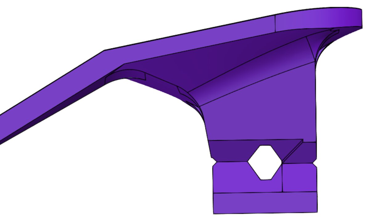 Each plunger has 2 contact patches. The front one presses the microswitch on the PCB. The back one touches the body of the microswitch right after it has been pressed. This firmly stops the button press and reduces mushiness.
Scroll wheel
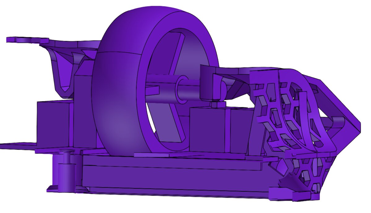 The scroll wheel serves two purposes. The scrolling and the middle button. One side of the scroll wheel is held by the encoder and the other one rests on the middle button. The middle button side requires additional support to stop the scroll wheel from going forward and backwards, but allows it to rotate and go up and down. Most mice solve this by having the support come from the bottom. This solution doesn't work for this mod, because the support would block the PCB from sliding in during assembly. I decided to support the scroll wheel from the top. The right paddle has a slot, which stops the scroll wheel from going forward and backwards, while allowing it to go down and also has enough space for the right click not triggering the middle click.
Front skates
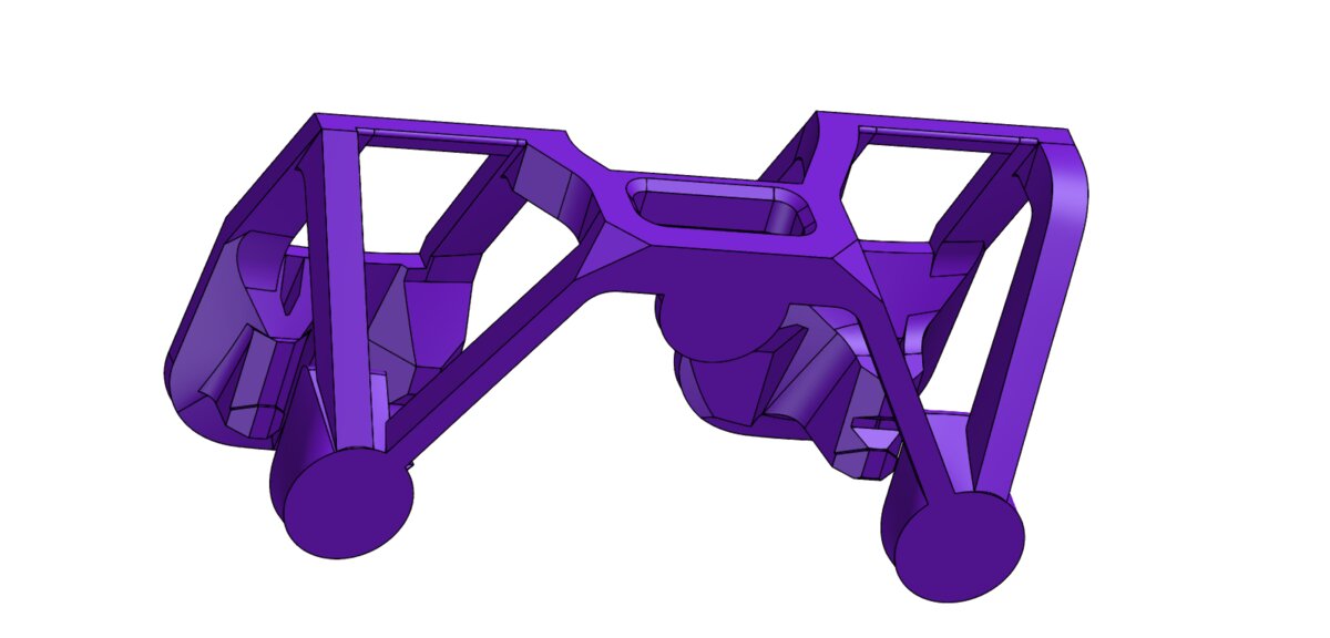 There are 3 spots for the dot skates at the front. 2 of them are under the index and middle fingers, which are mandatory and the third one is under the USB C and only needs to be used if the mouse is tipping to the front.
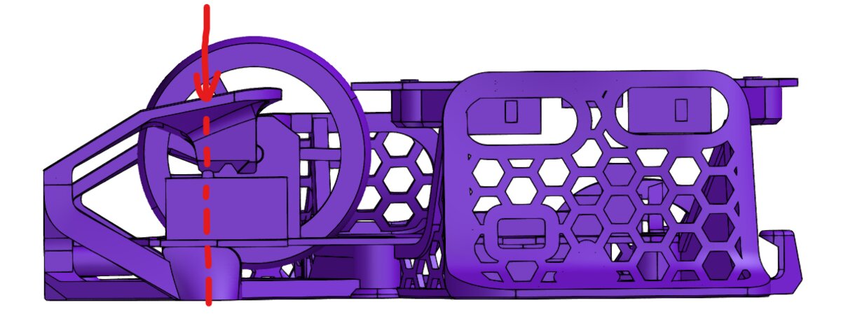 The 2 button skates are intentionally positioned right under the microswitches. This makes the load from the button press go straight down through the paddle, microswitch, skate block and to the mouse pad. Thanks to this the shell doesn't flex anywhere during the button press, which helps the clicks feel crisper.
Structure
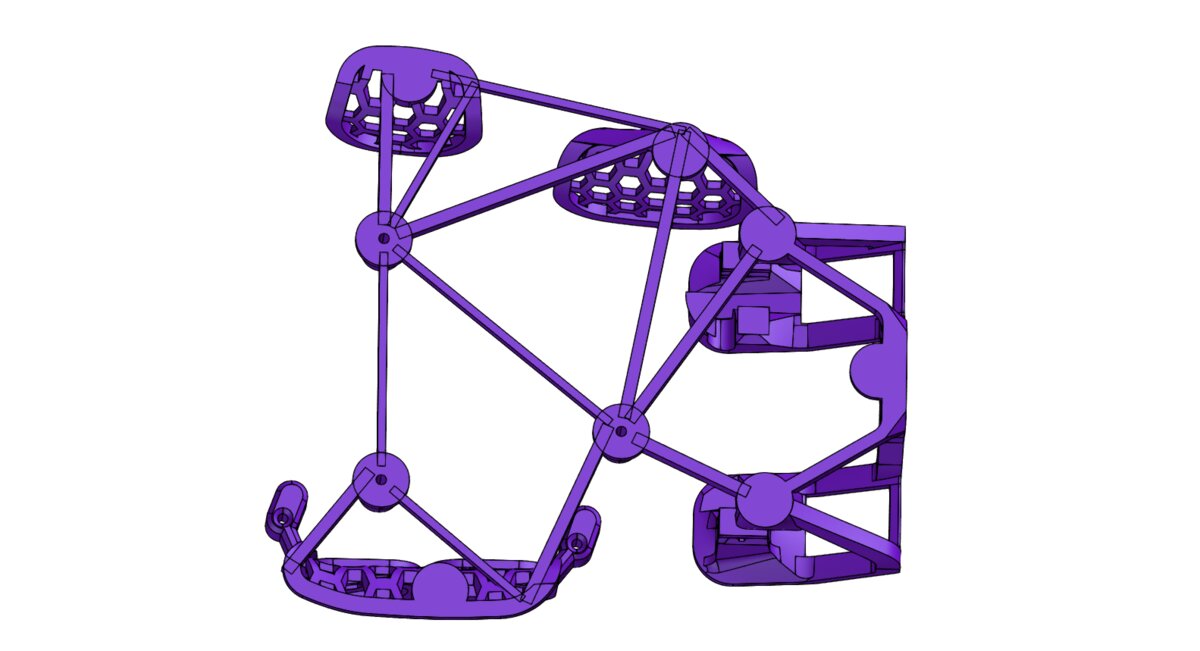 I decided to connect the grips, front section and the PCB screw points using simple lines at first. If well-designed, this should leave the structure stiff and lightweight at the same time.
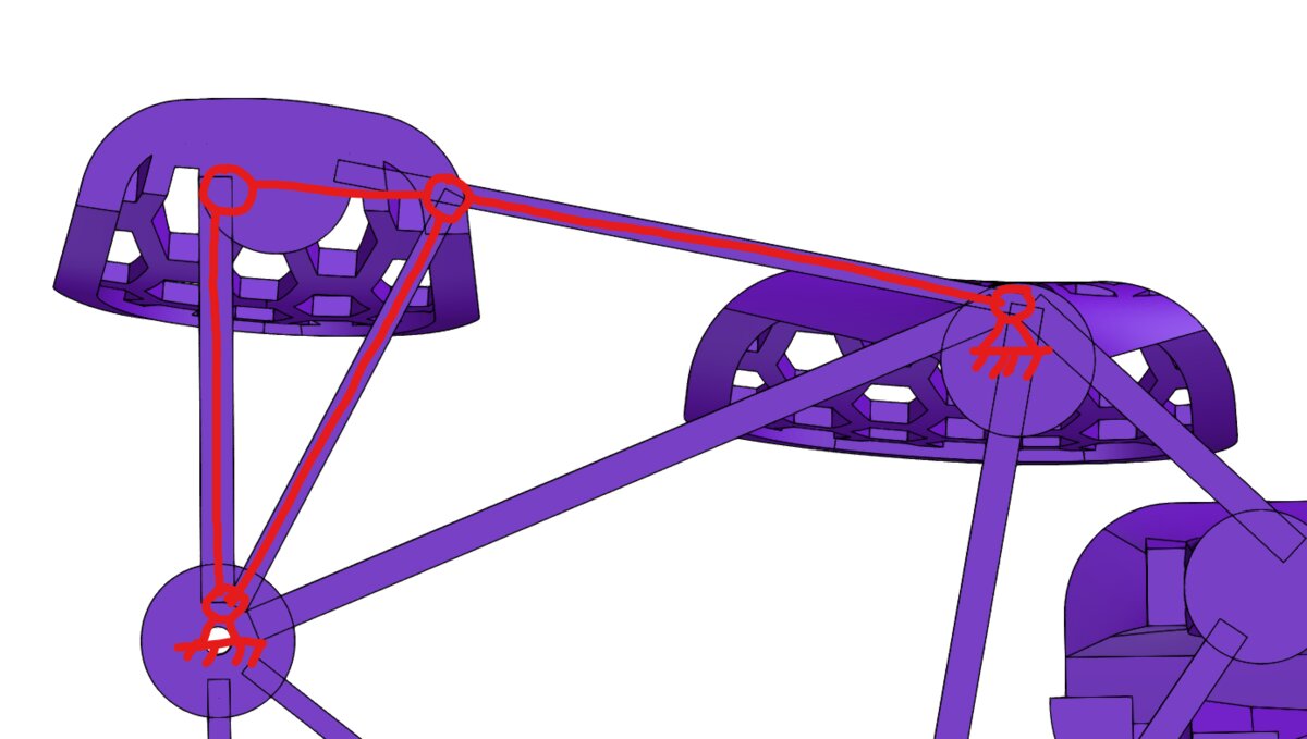 Each line is strong in tension and compression compared to bending. To prevent bending, we need to design each joint as if it was a revolute joint. This means that each grip needs 3 lines coming out of it at different angles and positions to fully define it.
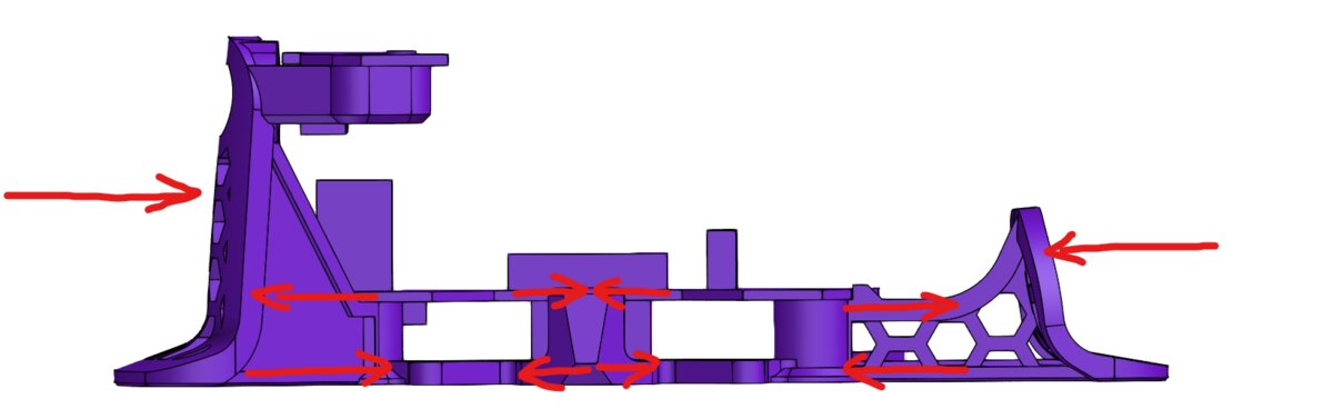 The force from gripping the mouse produces a bending stress in the structure. Each grip has ribs coming out of it to reduce the deflection due to bending. The ribs have "I" shape to optimize them for bending stress. Some ribs also have hexagonal cutouts to further reduce the weight. The ribs stop at the point where they contact the PCB. PCBs are usually made of glass fiber composite, which is stronger and stiffer than PLA. For this reason the PCB is used as a structural member. It is used for the compression side of bending, while the bottom 3D printed line is used for the tension side. Each rib contacts the PCB at the top to help transfer the load.
Printability
I tried to make this mod as easy as possible to print. I also tried to reduce the post-processing to a minimum. I did this by making all the overhangs printable and the rest bridgeable. The result is that you only need a couple of small tree supports to print this mod.
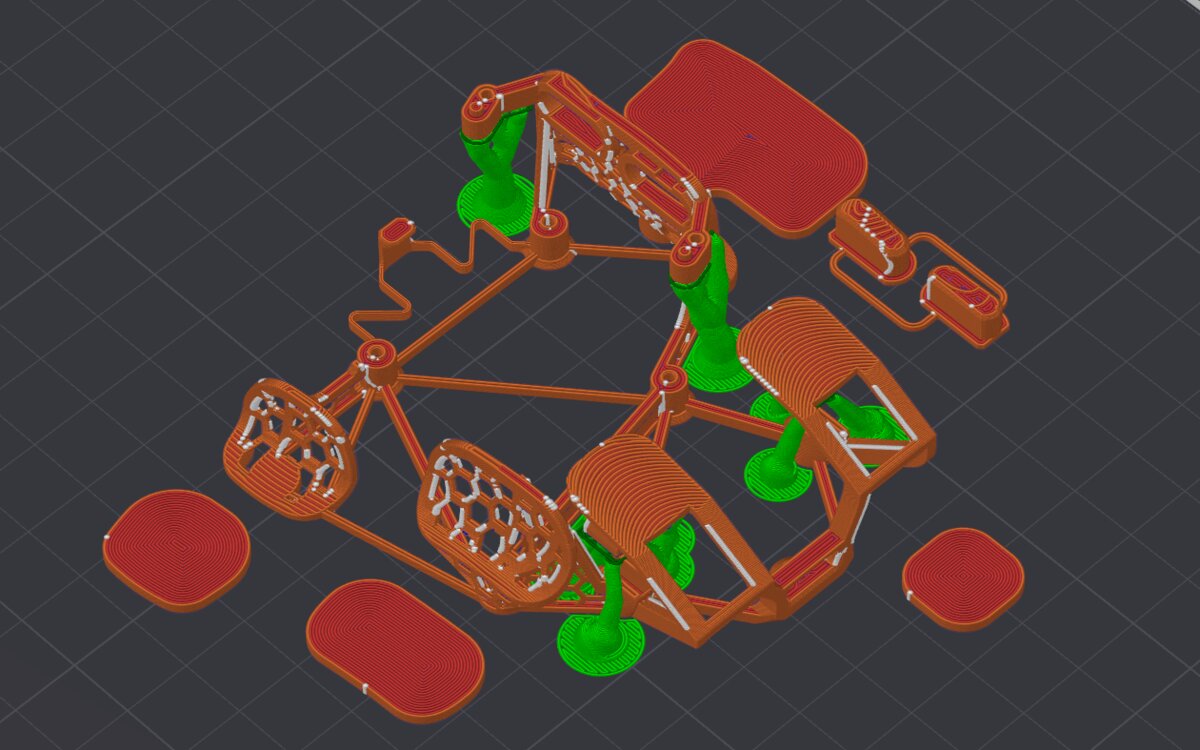
Print settings and assembly
Instructions for print settings and assembly are in the Printables post Kabrio mod or in the instructions video I made about this mod:
Content
A couple of content creators have made videos about this mod. Check them out if you are interested in what other people think: